freightliner air brakes My Wiring DIagram
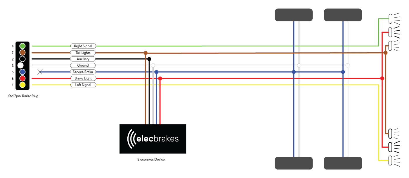
Elec Trailer Brakes Wiring Diagram
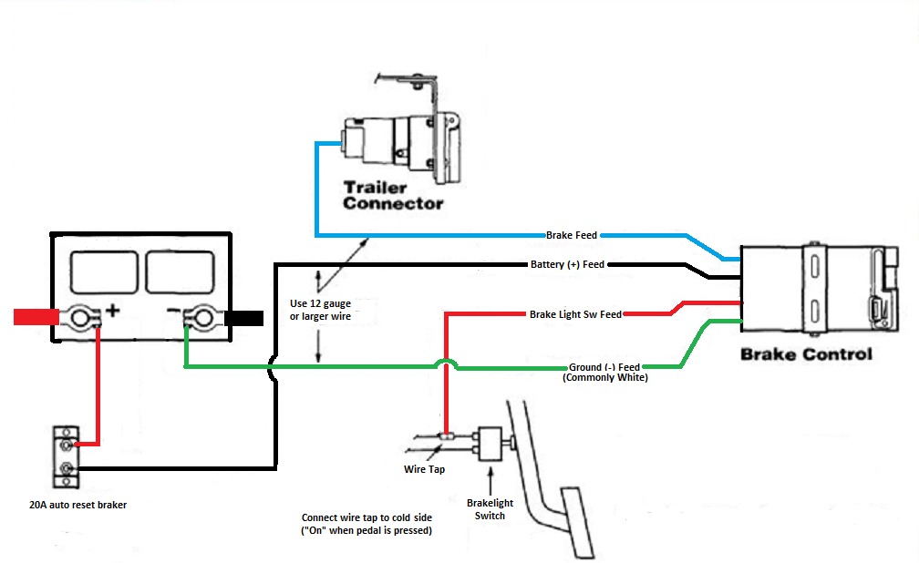
Brake Feed Wire Connection. The brake feed wire is responsible for delivering the electrical signal from the brake controller to the trailer brakes. Connect one end of the brake feed wire to the output terminal of the brake controller. Run the wire along the trailer frame, securing it with zip ties or mounting hardware.
Wiring Diagram For Trailer With Electric Brakes And Breakaway Wiring Draw And Schematic

The trailer brake wire is measured in gauge and depends on the trailer setup. The setup of the trailer determines the gauge of the trailer brake wire. For a gooseneck trailer, you will need at least a 10-gauge wire for the brakes. The steps for wiring a trailer brake are relatively simple and can be completed with basic tools.
freightliner air brakes My Wiring DIagram
Click for more info and reviews of this Dexter Trailer Brakes:https://www.etrailer.com/Accessories-and-Parts/Dexter/23-26.htmlCheck out some similar Trailer.
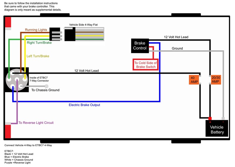
Trailer Mounted Brake Controller Wiring Diagram Wiring Diagram

Use electrical tape or wire loom to cover exposed wires, and secure them with zip ties or clamps to keep them in place. Additionally, consider installing protective conduit or tubing around the wiring to shield it from rocks, debris, or other potential hazards. 4. Check the brake controller.
Wiring A Trailer & Plug Commercial Trailers Qld Aluminium Machine

The colors for a 4-pin trailer wiring diagram are: White: Ground wire. Brown: Tail/running lights. Yellow: Left turn/brake light. Green: Right turn/brake light. 18-gauge wire is the minimum recommended size for the 4-way plug. This should be used for the lights.
Trailer Brake Wiring Schematic 7 Way
Trailer Wiring Connectors. Various connectors are available from four to seven pins that allow for the transfer of power for the lighting as well as auxiliary functions such as an electric trailer brake controller, backup lights, or a 12V power supply for a winch or interior trailer lights. Choose a connector that has the required number of.
2011 Chevy Silverado Trailer Brake Wiring Diagram prosecution2012

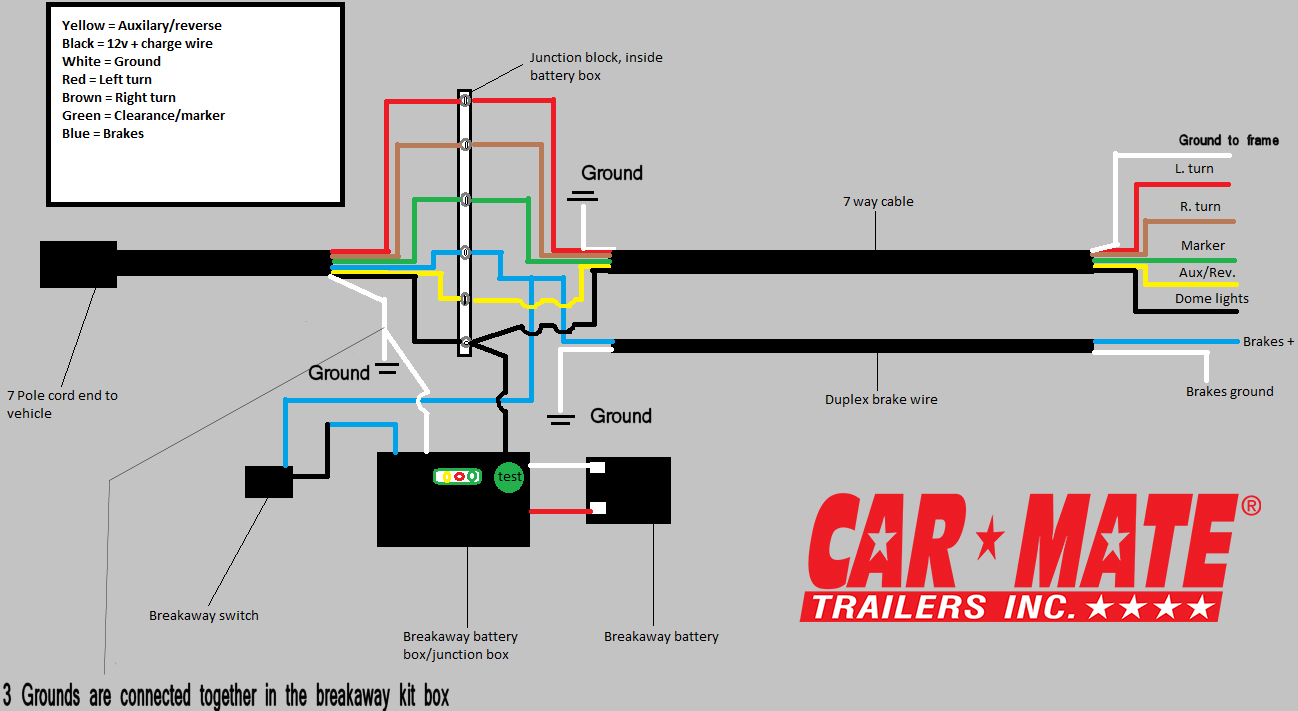
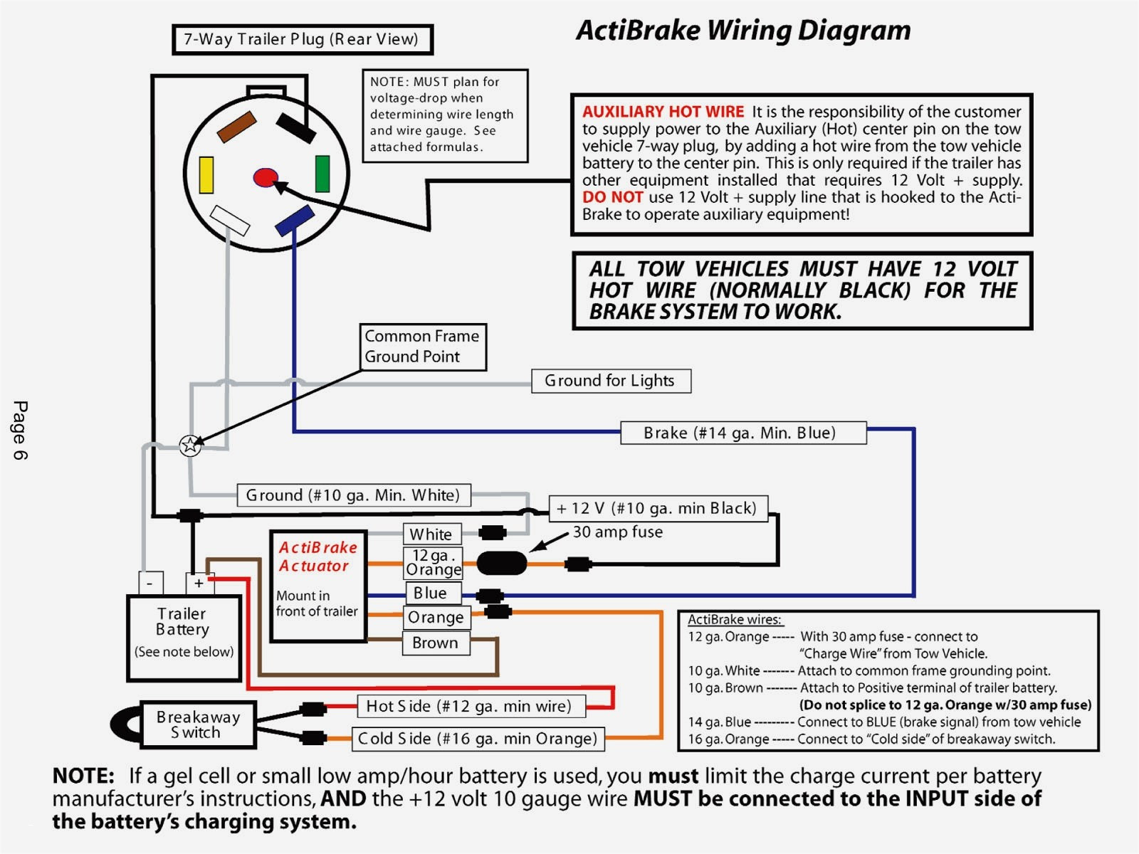
The concept of the "Breakaway" is to automatically apply brakes if a trailer comes disconnected from the tow vehicle.. superimpose this image over the Trailer Wiring Diagrams on that page. We suggest a 7-wire system so you have all the right connections. However, If your system has only a 5 wire plug, you can (in a pinch) wire the.
Universal Installation Kit for Trailer Brake Controller 7Way RV and 4Way Flat 10 Gauge
It's important to choose a wiring harness that matches both your vehicle and trailer's electrical systems. 5. Wire Strippers and Crimping Tool. To properly install the wiring for your electric trailer brakes, you'll need wire strippers and a crimping tool to remove insulation from the wires and securely connect them.
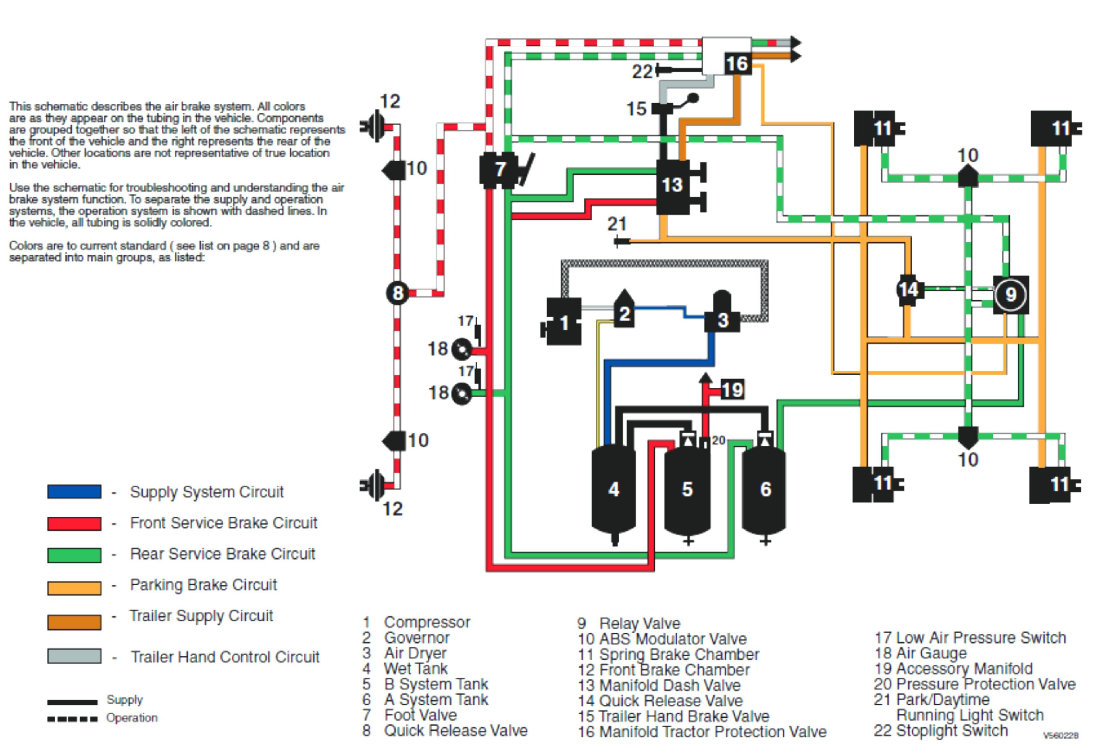
Trailer Air Brake Schematic

Learn how to wire a trailer hitch and electric brakes with this easy-to-follow video tutorial. You will need some basic tools and a few hours of your time.
Trailer Brake Plug Wiring Diagram Database Wiring Collection
A utility trailer wiring diagram with brakes helps you understand the basics of how the electrical components of your trailer work together to control the braking system. Typically, a utility trailer wiring diagram will include the following components: a power source, a brake controller, a brake switch, brake lights, turn signals, and ground.
How To Disengage Trailer Brakes? PostureInfoHub
Step 1: Disconnect the vehicle's battery. Start your splice-in brake controller installation by disconnecting the negative battery cable. This will help ensure your safety while working on the wiring system. It will also help protect your vehicle's electrical components from damage.
Electric Brake Breakaway Switch Wiring

The 5th pin, a blue wire, gives power to operate the trailer brakes. (The 5th wire can also be used to disable hydraulic brakes when in reverse.) Traditional Trailer + with Brakes = Use a 5-Pin Connector. 1-4 Wire the first 4 pins (White,. In the Trailer Wiring Diagram and Connector Application Chart below, use the first 5 pins,.
7 Pin Trailer Wiring Diagram With Brakes And Battery Wire A Trailer Wire A Trailer
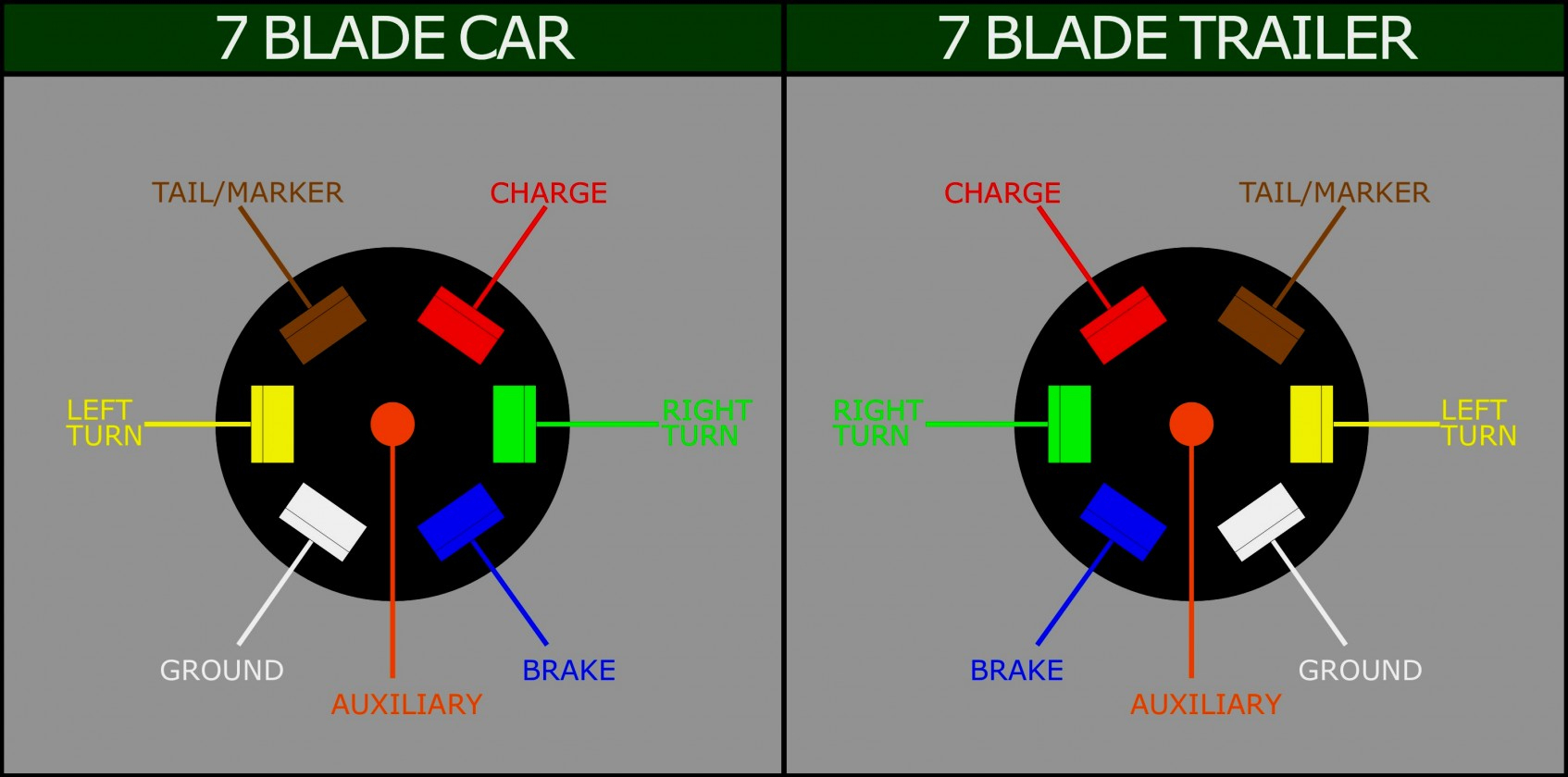
This trailer wiring guide comes complete with a color coded trailer wiring diagram for each plug type, including a 7 pin trailer wiring diagram, this guide walks through various trailer wiring installation solution, including custom wiring, splice-in wiring and replacement wiring. If your vehicle is not equipped with a working trailer wiring harness, there are a number of different solutions.
2004 Dodge Ram 1500 Trailer Brake Wiring Collection
If the trailer wiring is running down the left side of the trailer, then we splice the left side brake assemblies into the main electric brake power wire coming from the 7-way connector. We then run a jumper wire from the electric brake power wire to the right side brake assemblies (see photo). I recommend using 12-gauge wire, # 12-1-1, for the.
Dexter Trailer Brakes Wiring Diagram Wiring Diagram
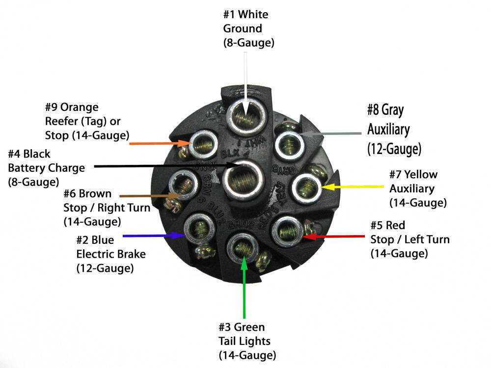
7-ways are some of the most common harnesses found on trailers. 7-ways provide the required running lights, turn signals, brake lights, and ground for the trailer. In addition, they provide three additional pins for a 12V hot lead, electric brakes, and reverse lights. Trailer wiring can be one of the most intimidating components of your towing.
Tekonsha Electric Trailer Brakes Wiring Diagram Wiring Diagram
Join Steph as she shares how to wired her Harbor Freight Utility Trailer! For materials and written post visit: http://bit.ly/trailerwireFull trailer assembl.